Hello guys,
First of all i'm going to say hy to everyone on this site, im a new member as you can see but i've been reading this forum threads for a few months ago when i bought a 2nd hand Megane 2 1.5dci.
Second let me tell you guys how good is this forum, lots of info available and the best part i see cooperation between all the members!
Well, now lets take care of busyness...this chitty (s instead of C of corse) keycard from Renault. The full story: when i bought the car I had 2 keycards, one only opened the doors and the other only started the car, so i had to walk around always with 2 keycards.
After this, 2 months ago the one that only started the card (this means that didnt give the message "Insert Card" on the dash) started to give me the message "Insert card" with the card on the slot, but during a few days i had to give some small taps on the card (when inserted) for the car recognize it. At this moment i thought: in a few days ill be screwed, the card will stop work, so i took my hands to work, opened the card that only unlocks the car. Now starts the electrical part and fortunately im a guy that can manage and measure and understand the philosophy of this keycards, (its similar to other manufactures).
Instructions to open the card:
Where, nothing on the web is as good as this ones, it took me a lot of work and you may do this sticky if you want, pictures and instructions. Please do not dry out your pockets and do it your self and exchange ideas with others:
![Image]()
![Image]()
![Image]()
![Image]()
![Image]()
![Image]()
Now its open...you will take 1h-2h, its normal...
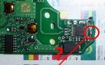
I've opened the card that only opens the doors and the coil (looks like a black coin) had a pin dried out from the PCB. Resolder it back and this card now starts my car without any problem, its totally functional!. Check this pictures as reference. The pictures below points out how to where the problem is and also explains how to solve the unlock/lock doors on your Megane:
![Image]()
Now, the development part, i opened the 2nd card and the problem where both, coil with dry solder from PCB and the contact from the battery dried out also. Well, just soldered them back and now it only opens and closes the door ok but still doesnt starts the card. This is extremely odd!. I've made some ohmic measurement on the pins of the coil. The measurement on the card that totally works one that works measure 95ohm (+-) and the one that doesnt work measure 56Kohm. This is a big difference! One more thing. I've placed both cards near the card reader (the one on the car that i think that produces an electrical field that goes thought the coil, the coil, no matter if the card is ok or not it should produce some voltage, its pure physics) installed on the car and the card that works we can measure 12V on the 2 pins of the coil, and the other one doens't even move.
My theory: even if there is something burned out on the board the coil must "produce" 12V like the other, unless the problem is the coil it self. Following this idea i've substituted the coil with a card that i managed to arrange (a free hands model, see pictures below to understand the differences). The problem remains, no 12V peak on when i place the card on the card reader and, of corse, "Insert card" message.
Now i need someone to cooporate with me, i'm willing to broke this card off just to explore it as far as possible in benefict of us all. Lets figure out what could be wrong in this situation. Thanks for your help. Now the pics...they are big because this way you can zoom it as you want...
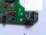
Model with hands free:
![Image]()
Model without hands free:
![Image]()
BR
Tomalamix
NOTE: Use this thread as you want, but please respect the work I've done and mention that. Thanks.
First of all i'm going to say hy to everyone on this site, im a new member as you can see but i've been reading this forum threads for a few months ago when i bought a 2nd hand Megane 2 1.5dci.
Second let me tell you guys how good is this forum, lots of info available and the best part i see cooperation between all the members!
Well, now lets take care of busyness...this chitty (s instead of C of corse) keycard from Renault. The full story: when i bought the car I had 2 keycards, one only opened the doors and the other only started the car, so i had to walk around always with 2 keycards.
After this, 2 months ago the one that only started the card (this means that didnt give the message "Insert Card" on the dash) started to give me the message "Insert card" with the card on the slot, but during a few days i had to give some small taps on the card (when inserted) for the car recognize it. At this moment i thought: in a few days ill be screwed, the card will stop work, so i took my hands to work, opened the card that only unlocks the car. Now starts the electrical part and fortunately im a guy that can manage and measure and understand the philosophy of this keycards, (its similar to other manufactures).
Instructions to open the card:
Where, nothing on the web is as good as this ones, it took me a lot of work and you may do this sticky if you want, pictures and instructions. Please do not dry out your pockets and do it your self and exchange ideas with others:


Now its open...you will take 1h-2h, its normal...
I've opened the card that only opens the doors and the coil (looks like a black coin) had a pin dried out from the PCB. Resolder it back and this card now starts my car without any problem, its totally functional!. Check this pictures as reference. The pictures below points out how to where the problem is and also explains how to solve the unlock/lock doors on your Megane:

Now, the development part, i opened the 2nd card and the problem where both, coil with dry solder from PCB and the contact from the battery dried out also. Well, just soldered them back and now it only opens and closes the door ok but still doesnt starts the card. This is extremely odd!. I've made some ohmic measurement on the pins of the coil. The measurement on the card that totally works one that works measure 95ohm (+-) and the one that doesnt work measure 56Kohm. This is a big difference! One more thing. I've placed both cards near the card reader (the one on the car that i think that produces an electrical field that goes thought the coil, the coil, no matter if the card is ok or not it should produce some voltage, its pure physics) installed on the car and the card that works we can measure 12V on the 2 pins of the coil, and the other one doens't even move.
My theory: even if there is something burned out on the board the coil must "produce" 12V like the other, unless the problem is the coil it self. Following this idea i've substituted the coil with a card that i managed to arrange (a free hands model, see pictures below to understand the differences). The problem remains, no 12V peak on when i place the card on the card reader and, of corse, "Insert card" message.
Now i need someone to cooporate with me, i'm willing to broke this card off just to explore it as far as possible in benefict of us all. Lets figure out what could be wrong in this situation. Thanks for your help. Now the pics...they are big because this way you can zoom it as you want...
Model with hands free:

Model without hands free:

BR
Tomalamix
NOTE: Use this thread as you want, but please respect the work I've done and mention that. Thanks.